How to Wire a Shed

Shed wiring
Quick Navigation
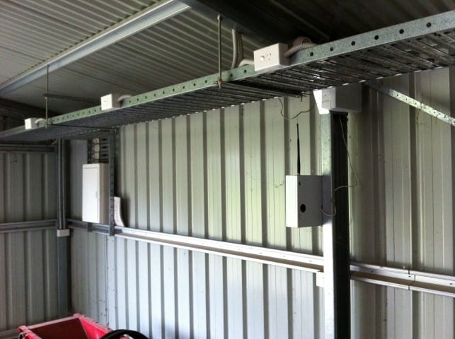
SO YOU HAVE A nice new shed to store all of your power tools and outdoor equipment. You decide to go out late in the evening in the middle of winter. It is dark. It is cold. It would be REALLY nice to have some overhead lights or a portable heater out there.
It is time to wire the shed up to your home's electrical system.
This article will give you the basics on how to go about wiring an outdoor shed. Every wiring project is different. This is general advice that might not apply to your situation. It is not a substitute for expert advice and if you are ever in doubt about what you should do it is time to talk to a professional electrician.
Wiring a shed is more complicated than most DIY home improvement projects. It requires planning and will likely take two weekends at least, more if you end up having to dig a long trench.
That said, in most cases wiring an outdoor shed is a project that a homeowner with some basic electrical knowledge can tackle on their own if they are willing to put in the work planning. We won't be talking about general wiring principles in this article; if you are in need of “wiring 101” help then you probably will want to tackle an easier project first.
Wiring a shed can be divided into the following stages:
- Planning – this is the most important and will take the longest
- Digging the trenches
- Shed receptacle wiring (including sub-panel if installed)
- Laying underground cable
- Internal home wiring
- Final connections
There are several options at each stage depending on your needs and your local electrical codes.
Speaking of electrical codes, the first part of planning is…
Know your Local Codes
The basic document for electrical wiring in the United States is the National Electric Code (NEC). The NEC is a living document and is updated every 3 years.
However, the actual rules that you are subject to are defined locally. Each locality will choose the elements of the NEC that apply to it. The National Electric Code is a minimal standard. Some jurisdictions will have more stringent requirements based on local conditions like weather or soil type. The most recent version is the 2014 NEC, but most places have not adopted it yet. Many places are still using the 2008 version.
The NEC is available through the National Fire Protection Association. Copies of the local electric code are usually available at the local library, or you can purchase one through Amazon.
You will also need to talk to the local electrical inspector at some point, so you might as well get it out of the way now. Many localities have procedures for homeowners that want to do their own work. Some will allow a homeowner to get a permit and do work on their own house but the inspections will be extra tough.
I really have to emphasize that you need to find out your local codes, because it will affect all of the subsequent plans. Some local codes require conduit for all underground wires, some do not. Some local codes allow PVC plastic receptacles but others require cast aluminum.
It may not seem important now, but doing everything to code will save you trouble in the long run. When you go to sell your house these are the type of things the inspector will be looking for. Having to dig up all of the electrical wire you ran years ago will be the last thing you want to do when you are in the process of moving.
Decide on your Needs
First, know why you want to have electricity in the shed. What you you want to run? How many lights? How many receptacles? A standard shed wiring project like a receptacle or two and some lights doesn't require a lot of power. What about power equipment or a welder?
If you want to be able to run a heater then we could be talking about 240V and a lot more power. Rather than running two or more circuits to the shed it may be more economical to run one larger circuit to the shed and install a sub-panel. From the sub-panel then you can run the two or three circuits that you need inside the shed.
Plan the Circuit
The first decision you need to make is whether to extend an existing circuit or create a new one. If an existing circuit just powers one or two outdoor receptacles and the shed is only going to have a light and a receptacle or two then it may be fine to extend the existing circuit.
On the other hand, if you are looking for multiple receptacles in the shed plus lights then you will need to run a dedicated circuit to the shed.
Things get more complicated if you have more advanced power needs or if you want to have heating or air conditioning in the shed. If you want to run equipment like a welder that requires 240 V service then you will need to run 240V to the shed.
At this point you will likely be looking at installing a separate sub-panel in the shed. You will run a single 250 V, 60A line to the subpanel and then break it out into multiple circuits from there.
Lay out your circuit
The details of laying out your circuit are beyond the scope of this article. They are unique to your individual plan. Here's one good article on planning electrical circuits for your home - Understanding Your Home's Electrical Load.
However, there are a few things I want to mention that are specific to outdoor circuits and sheds.
- Receptacles attached to a structure must be at least 1 foot off the ground and no more than 6.5 feet off the ground.
- If you have any freestanding receptacles outside then the receptacle should stand between 12 and 18 inches off the ground, although some local codes vary.
- Even more so than in homes, you should try to plan the circuit to minimize the length of cable runs. This will save you money (buying less wire), effort (less trench to dig), and safety(less wire means less potential for damage).
Which Wire?
An important feature of most outdoor wiring projects are the distances involved. The distance from the house to the shed could be longer than the entire run of the house.
For all residential wiring the wiring has to be a MINIMUM OF 12 GAUGE THICKNESS (remember, smaller numbers means thicker wire). In previous versions of the NEC 14 gauge wire was acceptable for 15 Amp circuits and in some local codes it may still be acceptable. But for best practices, it will be best to use the thicker wire.
For external structures you may be running wire a longer distance than usual. This could call for a thicker wire or a larger breaker. Longer wire means a greater voltage drop which the greater resistance in the thicker wire will protect against.
If the run is going to be greater than 50 feet then some electricians will recommend going up a wire size or two.
| amps | 25ft | 50ft | 100ft | 150ft | 200ft |
| 15 | 14 | 12 | 8 | 6 | 6 |
| 20 | 12 | 10 | 8 | 6 | 4 |
| 30 | 10 | 8 | 6 | 4 | 3 |
Source: cerrowire
Your diagram
If you are drawing a diagram for the local permitting office, follow their procedures and guidelines. Otherwise, mark on your diagram:
- The main service panel
- Utility lines (if known – otherwise discover them before digging)
- Label the types of wire – Outdoor wire needs to either be UF wire or in an external conduit.
- The receptacles and switches
Dig the Trenches
Before you begin to dig the trench, call the local utility companies and have them mark on your property where the lines are. You don't want to be digging and then find the kids screaming because you hit the cable TV line. Or even worse, hit a power line.
The national program is called “Call Before You Dig”. DIAL 811 (NOT 911) and you will be connected to the local program that handles marking utility lines, including power lines, telephone lines, and cable TV.
The burial depth varies by location and the type of conduit that you use to hold the wires. Don't be tempted to skimp on trench depth, even if you have hard clay soil that is difficult to dig.
The trench should be a straight line. No turns if you can manage it. The NEC limits the total number of turns in a conduit to 360 degrees total over the course of the whole run. In the local code it may be less.
According to the NEC, the minimum burial depth for PVC conduit is 18 inches. The depth for direct burial UF wire is 24 inches. The depth for metal conduit is 6 inches. Again, these are the minimums set by the NEC. The local minimums may be different.
How Deep to Bury Outdoor Electrical Wire
Install Boxes and Conduit
All switch and receptacle boxes should be rated for outdoor use. This means watertight. Water and electricity do not mix. The type of receptacle boxes that you can use depends on the local code. Some allow PVC boxes but others will require cast aluminum.
Start by doing the word inside the house. Install retrofit boxes and the cables between them if extending an existing circuit. Cut a hole to run cable to an outdoor GFCI receptacle. The receptacle needs to be right above the trench you dug. Run IMC conduit from the GFCI receptacle to 4 inches above the bottom of the trench, and then install a sweep fitting to the bottom of the trench.
Do the same thing on the shed.
This is also the point where you will install a sub-panel in the shed if you need to.
The video gives excellent instructions for installing a sub-panel next to the main panel. The main difference in installing a sub-panel in an external building is that an additional grounding rod is required.
Install Underground Wire
Exactly what you do at this stage depends on local code and personal preference. If the code allows, some people like to lay UF cable directly in the ground. Make sure that you dug to the proper depth for laying UF cable. The UF stands for “Underground Feeder” and is a cable that is designed to be watertight and resist the elements under the ground. NM wire, the standard cable inside homes, cannot be used.
UF wire only needs to be used in the outdoor portions of the circuit. The part in the shed and in the house can use the standard NM wire.
If you are using conduit, pulling the electrical cable through the conduit will be the second least fun part of the project (after digging the trench). This video, though over 10 minutes long, is a good video on pulling wire through conduit using string and rope.
Extension Cord… Just Say No
This looks like hard work so far. At some point it could become tempting to use a male to male extension cord to connect the shed to the house power. Please resist this temptation. Some people claim that this can last for years, but the extension cord is not rated for continual use. Especially not in the elements. It will turn into a fire hazard, if not for you then for the next owner.
Making the Final Connections
Make sure you know what the electrical inspector needs to see. Different locales will require inspections at different points in the process. Before you close everything up the inspector will need to take a look at it.
Wire up the switches and the outlets. Make the final connection to the main circuit breaker. If you made it through the rest of the steps, then you can get through this one without any problem.
When to Call an Electrician
Most of these components can be installed by a homeowner with a basic knowledge of electrical wiring. You may need to call an electrician if:
- You want a sub-panel and are not comfortable installing one yourself
- You do not see a good way of making a single straight line from the house to the shed. This is especially true if you are using conduit to run the wires. Bending conduit properly is hard, but do-able if you take your time
- You are not sure how to do proper load analysis
- Or your load analysis shows that that you do not have adequate capacity in your main breaker. It may be time for an upgrade
- You cannot acquire or cannot understand the local building code
Thanks for reading. I hope you go something out of this.
Please be safe, and if you are unsure, call an electrician!
ZacsGarden – How to Build a Shed
Attributes:
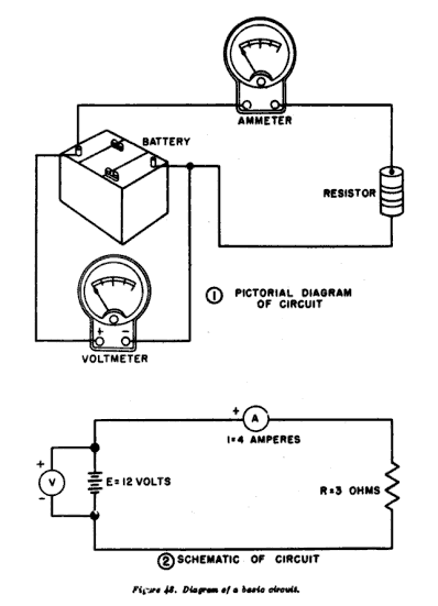
“Circuit diagram – pictorial and schematic” by United States. Dept. of the Air Force – Operation and Maintenance of Diesel-electric Locomotives. Licensed under Public domain via Wikimedia Commons – https://commons.wikimedia.org/wiki/File:Circuit_diagram_%E2%80%93_pictorial_and_schematic.png#mediaviewer/File:Circuit_diagram_%E2%80%93_pictorial_and_schematic.png
Related Articles:


